Gate Valve vs. Globe Valve vs. Check Valve – Principles, Applications, and Differences
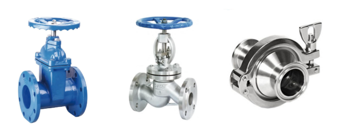
Gate valves, globe valves, and check valves are three of the most fundamental and common types of valves. While their external appearances can sometimes be similar, their internal structures, working principles, and core missions are distinctly different.
What is a Gate Valve?
A gate valve is intended for the ON/OFF operation of fluid flow, involving either fully open or fully closed states. Imagine a gate moving up and down within a pipeline – this is the most intuitive image of a gate valve. Its core design features a wedge or parallel gate disc (see Fig. 1). By rotating a handwheel or actuator, the valve stem is driven to move the gate disc perpendicular to the fluid flow direction. When the gate is fully raised, the flow path is completely unobstructed.

Fig 1. Working principle of gate valve
The flow direction does not change as fluid passes through a gate valve. When a gate valve is partially open, the disc is prone to vibration. Gate valves are therefore suitable for fully open or fully closed applications and are not designed for scenarios requiring flow regulation. Additionally, due to their slow opening and closing speed, they are not suitable for pipelines requiring emergency shut-off.
However, gate valves offer good sealing performance and are thus often used in pipelines requiring tight shut-off. They are well-suited for applications demanding minimal pressure drop and involving infrequent operation, such as main water supply lines in cities or raw material transport pipelines in the chemical industry.
What is a Globe Valve?
Unlike gate valves, which are unsuitable for flow regulation, globe valves are commonly geared towards systems requiring frequent adjustment of flow rate or pressure. Unlike the straight-through design of a gate valve, the internal structure of a globe valve is more tortuous (see Fig. 2). After entering the valve body, the fluid must first flow upward, bypass the valve seat, and then change direction to exit. This “S”-shaped flow path design inherently increases flow resistance, but it is precisely this characteristic that gives the globe valve excellent regulating capabilities. Its closing member is a plug-type disc, often flexibly connected to the stem, allowing it to seat precisely onto the valve seat.

Fig 2. Globe valve structure diagram
Globe valves offer reliable sealing performance and are also suitable for flow regulation. They are typically installed at pump outlets, upstream of control valve bypasses or flow meters, and other locations requiring flow adjustment. Globe valves must be installed with the flow direction “low-in, high-out” (flow entering below the disc and exiting above it). If installed incorrectly, any debris in the pipeline can get trapped on the inlet side of the disc, causing wear and preventing tight shut-off. Furthermore, if the medium does not pass through the regulated path around the disc, proper flow control cannot be achieved.
What is a Check Valve?
If gate valves and globe valves require manual or external power for operation, then check valves operate completely automatically. Their design has a single goal: to prevent backflow of fluid. They contain no valve stem or handwheel; their opening and closing rely entirely on the kinetic energy of the fluid itself (see Fig. 3).

Fig 3. Check valve working principle
The two most common types of check valves are Swing-type and Lift-type (see Fig. 4).
- Swing Check Valves have a disc hinged at the top, swinging like a one-way opening door. When fluid flows in the forward direction, its pressure pushes the disc open. Once flow stops or reverse flow occurs, the disc closes swiftly under the backflow pressure and its own weight.
- Lift Check Valves feature a disc that sits on the valve seat. Fluid pressure lifts the disc; when the pressure drops, gravity or a spring force returns the disc to the sealed position.

Fig 4. Check valve types
Check valves are widely used at pump outlets to prevent media backflow and water hammer from impacting the pump when it stops. They are also used to prevent media interchange between systems of different pressures, making them indispensable components for system safety.
Comprehensive Comparison
|
Characteristic |
Gate Valve | Globe Valve |
Check Valve |
|
Core Function |
ON/OFF (Isolation) | Regulation & Shut-off |
Prevent Backflow |
|
Working Principle |
Gate disc moves perpendicular, creating straight flow path | Disc moves to alter “S”-shaped flow path opening |
Disc opens/closes automatically via fluid pressure differential |
|
Flow Regulation Capability |
No | Yes |
No |
|
Installation Direction |
Usually not critical | Strictly “Low-in, High-out” | Strictly unidirectional flow |
| Operation Method | Manual, Electric, etc. | Manual, Electric, etc. |
Fully Automatic |
These valve family serve different purposes, but in complex industrial piping systems, they are often seen working together.
A gate valve is typically installed on the suction line of a pump. This location requires minimal flow resistance to avoid pump cavitation, and this valve is typically only closed for maintenance, aligning with the gate valve’s application scenario.
A globe valve is installed immediately following the pump discharge first. It acts as an “isolation valve” or “service valve,” used for slow pump loading during start-up, flow regulation, and isolating the check valve and pump for maintenance.
A check valve is installed after the globe valve, and a wafer-type check valve is commonly used in practice. Its role is to close swiftly if the pump shuts down suddenly, preventing high-pressure backflow from impacting the pump impeller and causing “water hammer” and reverse rotation damage.