Structure of Pneumatic Ball Valves
A pneumatic ball valve is a device that uses compressed air to open or close a line of flow rapidly by means of a rotating ball. The performance of this machine depends on the precise and reliable work of each of its parts.
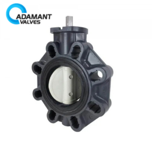
Valve Body Assembly
The pneumatic valve usually comprises essential parts such as the valve body, the ball, the seat, and the stem; a three-piece valve, for instance, which consists of a left and a right body section and a middle section that carries the ball, is made up of left and right body sections and a middle section that carries the ball. This design allows for easier maintenance. Connection ports on the valve body can be threaded, flanged, welded, or use other methods, depending on the application requirements.
This type of valve is suitable for controlling media like water, oil, gas, and generally corrosive liquids or steam in pipelines. It works by using an external pneumatic actuator to turn the stem, which rotates the internal ball 90 degrees to quickly open or close the line.
Handwheel Gear
The handwheel gear is a crucial backup device that allows manual valve operation during a loss of air supply or system failure. The hand wheel is usually clearly marked with the signs “open” and “closed,” its principal function being to switch between manual and automatic control modes.
To activate the shift, pull up the lever. Then turn the handwheel, the inner shaft, and the valve stem will be turned directly by the movement of the handwheel.
If the handwheel is then turned, the handwheel turns freely without turning the shaft, and the valve is under automatic control by the pneumatics.
Solenoid Valve
The solenoid valve is a low-voltage electric switch used to regulate the air supply to the valves. When an electric signal is given, it rapidly changes the air path, sending the compressed air into the different chambers of the actuator, opening or closing them. There are two main mountings: in-line (pipeline) mounted, which generally has one air inlet and two exhaust tubes on the bottom, and requires hoses to connect the valve to the actuator for more flexible and flexible mountings.
Limit Switch
The limit switch, also known as a position indicator, is an electric switch that gives information from the position of the valve to the control system. It is mainly constituted of cams, microswitches, and contact blocks.
Its lower drive shaft connects to the actuator’s output shaft and rotates 90 degrees with it. When the valve reaches the fully open or closed position, an internal cam triggers the corresponding micro-switch to make or break contact. This switch signal is wired to a PLC, creating an open or closed circuit. This allows the valve status (indicated by a light on/off in the control room) to be monitored remotely.
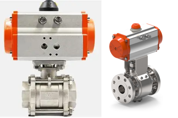
Pneumatic Actuator
The pneumatic actuator serves as the primary power source that actuates the valve. Its casing typically contains two air inlet ports positioned to facilitate the “open” and “close” motions. Functioning through compressed air, it moves an internal piston or a rack-and-pinion mechanism, producing torque that causes the upper output shaft to rotate by 90 degrees. This rotational movement is directly transmitted via a drive shaft to the valve or the handwheel gear situated below, enabling coordinated operation. Mounted at the top of the actuator is the limit switch, which provides essential position feedback, while the lower connection links to the main valve body or the handwheel gear, completing the drive mechanism.
Conclusion
A thorough understanding of these components’ design and roles enhances the ability to select, troubleshoot, and maintain valves effectively, ensuring consistent and dependable performance within the fluid control system.